GOLT !
RED LIGHT DISTRICT - Eurorack Sequencer
(click images to enlarge)
Sections:
- About RLD
- Documents
- New Firmware Options for controlling other analogue sequencers
- Where to Buy (Updated 2nd March 2019)
- Videos
- Your Pictures of RLD in the Wild!
ABOUT - RED LIGHT DISTRICT
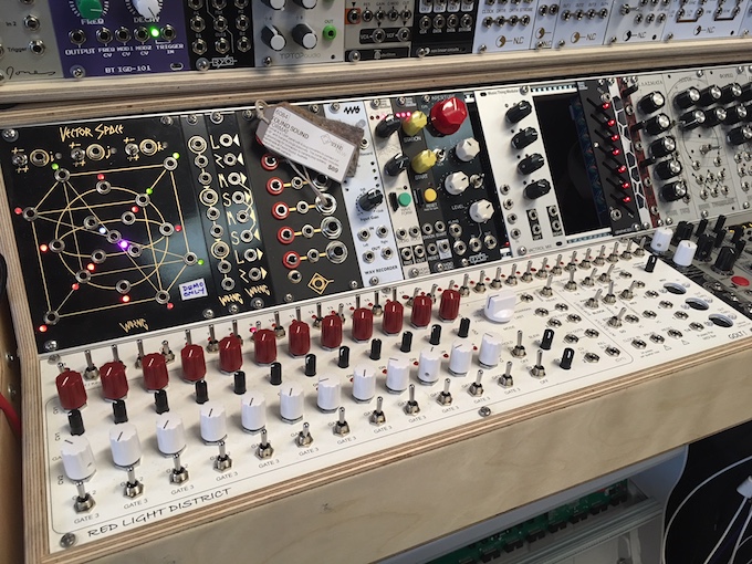
RED LIGHT DISTRICT (RLD) is an 84HP traditional CV/Gate Sequencer that can be synchronised at different ratios to MIDI clock. Its main purpose is to create patterns that are in-time and length-related to MIDI clock. It can act as a MIDI Master using its own internal clock as a reference, or an external clock input. When slaved to MIDI, the MIDI OUT's automatically switch to THRU’s and the second MIDI OUT/THRU can also to emit DinSync. The sync ratio can be changed so that each pattern of 16 or 32 steps can take either 1, 2 or 4 MIDI bars to complete. Mode changes are quantised to the start of each pattern so synchronization is maintained with other sequencers.
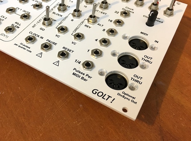
On-board, two digitally controlled analogue sequencers work together to produce CV's and Gates in pattern based form. The main difference compared to traditional analogue sequencers is the ability to create time quantised spaces in between the gates, as well as the gates themselves. This effectively doubles the number of equivalent analogue steps it has, because each gate has it's own dedicated variable space after it. This allows a full ADSR to be used for envelope control, because the gates resemble a more realistic keyboard signal (key ON/OFF) rather than each gate occurring immediately one after the other (like in traditional analogue sequencers).

There are two CV's, three gates and six synchronized clock divider outs. There’s voltage control over direction, pattern, pause and reset on the timing sequencer (the 32 Step Sequencer), and voltage controlled slew on the pitch sequencer (the 12 Step Sequencer). Both CV’s on the pitch sequencer have switchable S&H circuits and CV1 (normally used for pitch) has both course and fine tune knobs to allow up to 9 octave jumps between steps, while still retaining fine control well within a semitone.
Special features include time quantised muting, clock dividers that synchronise to MIDI, internal clock, or external clock. And NO menu's at all. All functions can be changed while the sequence is running, including note insertion that doesn't change the sequence length (because the pattern length is sync'd to 4/4 MIDI).
Both on-board sequencers have comprehensive direction control, including a Brownian Random and Voltage Addressed Stepping on the 12 step sequencer. Both CV’s can also be used as a rudimentary Attack/Release generators; with global slew, peak-height and width, adjustable per step.
Power Consumption:
- +12V: 125mA (90mA when idle)
- +5V: Not Used (there is a +5V regulator on board)
- -12V: 7mA
DOCUMENTS
Red Light District User Manual (2MB, v2.1)
Red Light District DIY Build Manual (High Resolution Pictures, 123MB, v2.1)
Red Light District DIY Build Manual (Low Resolution Pictures, 14MB, v2.1)
The DIY Bill of Materials is available in three formats:
- RLD BOM for Excel (498KB, v2.5.04)
- RLD BOM for Numbers (230KB, v2.5.04)
- RLD BOM PDF (73KB, v2.5.04)
The latest version of the BOM (2.5.04) clarifies the resistor specs. All resistors are the standard through hole 1/4W size (7mm x 2.5mm).
Service Notes:
- Service Note #01 - How to adjust LED brightness (27KB)
If you are considering purchasing a sequencer or kit, download the packing list so you can see what you are going to get:
- RLD Bare Bones Kit Packing List (34KB)
- RLD Partial Kit Packing List (47KB)
- RLD Fully Built Packing List (26KB)
Here's an example of the final test certificate for the fully built version: RLD Final Test Certificate (41KB)
The packaging for all options is very similar; even the DIY versions come with the official box and bubble wrap so you can pack it properly once it's built.
FIRMWARE OPTIONS - RED LIGHT DISTRICT
There are now two additional firmware options besides the standard firmware. These change one or more of the clock divider outs into outputs that can be used to control other analogue sequencers. These options are available through me only at this stage (see the about page for new contact details). The process of changing the firmware is very old school and requires the swapping of the 28 pin processor labelled "SYNC".
The options are as follows:
- Option 1: Reset Trigger Out. This changes the 1/4 pulse per bar divider out into a Reset out. The sequencer will send a 10ms trigger pulse whenever a MIDI STOP command is received or the sequencer is stopped via the STOP/GO toggle switch.
- Option 2: Reset Gate Out and Inverted 16 Out. This is a special edition made for compatibility with the soundmachines DC1drumcomputer. I use that module for general triggers but it has the most "non-standard" sync characteristics I've ever seen. This firmware update is the best I can do to try and control the DC1. RLD's 16 pulses per bar clock output has now been inverted and sent out the 1 pulse per bar output. This allows the DC1 get clock triggers off the negative edge of the 16th pulse. The Reset signal is still sent out the 1/4 clock out as in Option 1, but it is now a gate to try and stop the DC1 from starting early. The main problem with the DC1 is pressing start or sending a start causes it to increment a step BEFORE a clock pulse has even been received. Sometimes on starting it still gets it's knickers in a knot, but I think I've done OK to make it behave as a slave.
WHERE TO BUY

The GOLT! RLD sequencer is available pre-built from Patchcable for $895 AUD (includes GST). I have sent them a very rare black RLD so keep an eye out for that on their website. The links here will take you straight to the RLD page on patchcable.
The DIY kit is now available from FOUND SOUND!
Bare Bones Kit $319 AUD (includes GST) - Just absolute minimum required to start building. The panel (2mm Aluminium power coated white and screen printed), two PCB's and three processors. Please see the BOM, packing list and build manual for more detail.
Please note: The prices for the toggle switches can vary between $2.20 and $5.00 each (I have no idea why). But they quite cheap at the moment. If you ever get stuck let me know (via Mumbulla Modular) and if I have some spare I'll send you some of mine. I buy them in bulk (2000+ at a time) so my prices are more stable.
Partial Kit $539 AUD (includes GST) - Everything in the Bare Bone Kit PLUS all toggle switches (54), pots (39), mono jacks (20), DIN jacks (3), rotary switch (1) and all board connectors, headers, mounting hardware etc... Basically all the expensive or hard to get stuff is included, potentially at a big discount. What IS NOT included is all passives (diodes, resistors, capacitors) and all IC's (mostly 74HC logic and some linear stuff). Please see the BOM, packing list and build manual for more detail.
If you are in Melbourne (Australia) you can try out RLD yourself! There is one in FOUND SOUND's massive demo system.
FOUND SOUND will also be selling fully built RLDs for $895, so stay tuned for that. I'll post an update once they are in stock.
And if you are in the US, the RLD partial DIY kit is available from Modular Addict. Please check it out!
RLD VIDEO'S
Here are some video's of the pilot version in action. It was basically the same as the release version, except it didn't have an input for an external clock. I had a lot of input from users and this was the feature that was requested the most.
And next are some video's of earlier prototypes. I spent about 18 months figuring out what I did and didn't need to include. At first I just designed a sequencer that had everything I ever wanted. But ultimately all those things were never going to fit into 84HP; not with one switch per function anyway. And there was no way I was going to make a sequencer with menu's or soft-keys. I spent a long time jamming with it, getting to what features I used the most. In the end this time proved to be extremely valuable as I found out some things were really not needed, and it also made be think of a couple of extra features that didn't even cross my mind before that.
RLD IN THE MEDIA
- 2018-3-26 ~ ASK.AUDIO Red Light District Is An Analog CV/Gate Sequencer For Eurorack by Rounik Sethi
- 2018-3-35 ~ Synthtopia ‘Red Light District’ A Knobtactular Monster Sequencer For Eurorack Systems
- 2018-3-25 ~ GEARNEWS Red Light District (RLD) Eurorack sequencer by Robin
- 2017-3-18 ~ Synthtopia RLD Superbooth17 Sneak Preview
RLD in the wild - Pictures
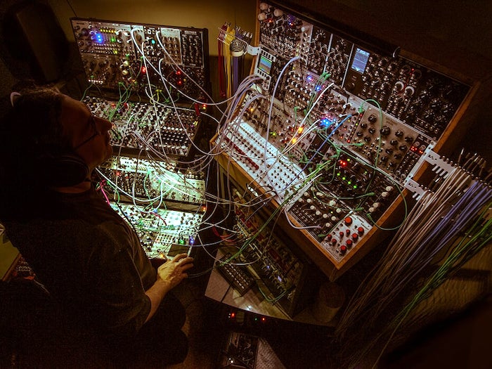
The first picture of an RLD in the wild comes from Mr Rachele.
He's just released his second Album on Bandcamp. Click here to check it out!
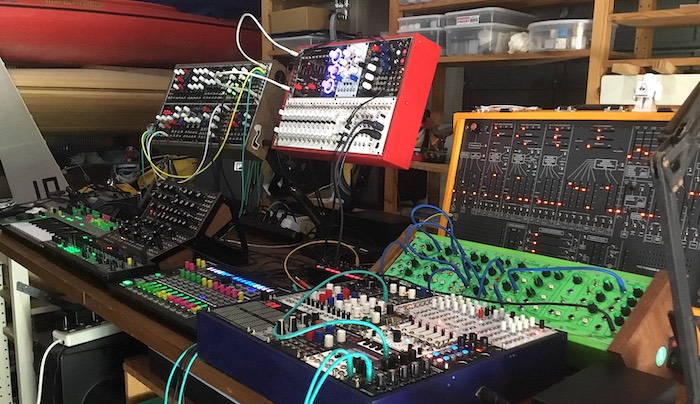
The next picture comes from Chris in Australia.
Here's a picture of my two RLDs. They look so naked without the patch cables!


